
04 · ELECTRICAL & SAFETY
Electrical, Testing & Safety
Some of the most important work is invisible: an installation that is tested, documented and compliant. We test complete installations and resolve faults, design dedicated electrical boards, certify installations to utility, fire-service and insurer requirements, and manage connection upgrades.
04 · SIMULATOR
What do we test in an installation?
Pick a component in the diagram to see what is tested, with which instrument and what counts as a pass.
Diagram of an installation: meter, main board, RCD, final circuits, earthing and a solar system. Choose a component with the buttons.
RCD (30 mA)
- Test
- Trip time at the rated residual current (IΔn) and its multiples, plus a ramp test
- Instrument
- RCD tester
- Pass criterion
- Trips within 300 ms at IΔn, 150 ms at 2·IΔn and 40 ms at 5·IΔn
- Reference
- IEC 61008-1 · IEC 60364-6 · IEC 61557-6
Insulation fault demo
Current leaks to the metal enclosure of an appliance. What happens with and without an RCD?
When animated, the trip is slowed 40 times. Trip times are typical values for a healthy device, not measurements.
Which connection size do you need?
The final size is set with the utility based on a detailed design.
04 · CAPABILITIES
What we do
Installation testing
Testing complete installations, finding and fixing faults, with a clear findings report.
Electrical boards
Dedicated boards designed for machines, plants and buildings.
Connections & utility
Connection upgrades and follow-through with the utility connections and inspection teams.
Safety
Certificates to fire-service and insurer requirements, and safe-work practice on every site.
04 · IN DEPTH
In depth
Anatomy of an installation: from the supply point to the socket
Every installation is a chain. The meter sits at the supply point; from there the supply runs to the main board and main breaker, then to the sub-boards, and from them to the final circuits that feed sockets, lighting and machines. The protective devices are coordinated so that the one nearest a fault trips first (selectivity), and a fault on one circuit does not black out the whole building. RCDs protect the final circuits.
The size of the utility connection follows from the current. Take the connected load, multiply it by the diversity factor, since not everything runs at once, and divide by √3, the line voltage and the power factor: I = P·1000·k ÷ (√3·400·PF), with P in kW. Round the result up to a standard connection size, 25 A to 630 A in the simulator; the final size is set with the utility. In the simulator above you can run this calculation, and pick a component in the diagram to see what is tested in it.
Voltage drop is limited by regulation too: under the Israeli final-circuits regulations (1984), regulation 2(e), the drop between the consumer’s terminals and any point of use in the installation must not exceed 3% of the nominal grid voltage. In a long or undersized cable the drop grows and equipment may run on too low a voltage, so it is checked at the design stage.
Sources: IEC 60364 series · Israeli Electricity (Final Circuits Supplied at up to 1000 V) Regulations, 1984
How an RCD saves lives
An RCD constantly compares the current going out on the phase with the current coming back on the neutral. Both conductors pass through a toroidal transformer, and as long as the two currents are equal, their magnetic fields cancel out. If part of the current does not come back, it is leaking to earth, possibly through a person. The difference creates a field in the toroid, and the device disconnects the circuit.
An RCD for personal protection has a rated residual current (IΔn) of 30 mA. Under IEC 61008-1 it must trip within 300 ms at IΔn, 150 ms at 2·IΔn and 40 ms at 5·IΔn, and it must not trip at half of IΔn or less, to avoid nuisance tripping. In Israel, the switchboard regulations (1991), regulation 29(d), require every final circuit in a dwelling to be protected by a 30 mA RCD. Press the test button from time to time to check that it trips.
A transformerless solar inverter can pass DC leakage current, so according to manufacturer data it needs a type B RCD or residual-current monitoring built into the inverter under IEC 62109-2. In TT earthing, IEC 60364-4-41 adds a rule: the earth resistance times the RCD’s rated residual current must not exceed 50 V, and in Israel the earthing regulations also limit the electrode resistance to 5 Ω at most. In the fault demo in the simulator above, you can inject a leak and see what happens with and without an RCD.
Sources: IEC 61008-1 · IEC 60364-4-41 · Israeli Electricity (Installation of Switchboards up to 1000 V) Regulations, 1991
Thermography: finding a fault before it burns
A loose connection or an overloaded component heats up before it fails. A thermal camera sees that heat without touching anything and without shutting the installation down. For the image to mean something, the board is scanned under load, at least 40% of its rating, and each component is compared with a similar one under the same load, such as the three phases of the same breaker.
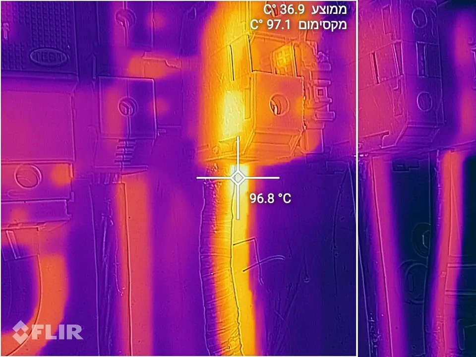
Severity is graded by the rise over the similar component, per NETA table 100.18: 1–3 °C is a possible deficiency, 4–15 °C a probable one, and over 15 °C a major one. In the photo, from one of our inspections, a cable connection reached 96.8 °C while the average temperature in the same frame was 36.9 °C. It is one example from the field, not a statistic.
Thermography takes experience. Shiny copper emits little infrared radiation (it has a low emissivity), so it reads colder on the camera than it really is, and someone who does not know this can miss a hot spot. Solar modules have their own conditions under IEC TS 62446-3, for example an irradiance of at least 600 W/m² on the module plane. In the simulator above, clicking the main board shows thermography as part of its test.
Sources: ANSI/NETA MTS, table 100.18 · NFPA 70B-2023 · IEC TS 62446-3:2017
04 · PROCESS
How it works
- 01
Request & data
Collecting drawings, requirements and the purpose of the test.
- 02
On-site test
Testing the installation by a licensed inspector.
- 03
Report & findings
A structured report with findings and recommendations.
- 04
Repair & design
Carrying out repairs or designing the required changes.
- 05
Approval & handover
Re-test and delivery of the certificates.
04 · CLIENTS
Who it is for
- Factories and industrial buildings
- Public buildings and institutions
- Retail and offices
- Contractors and developers
04 · FIELD
From the field
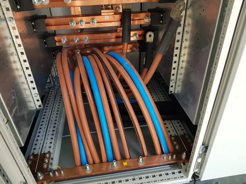
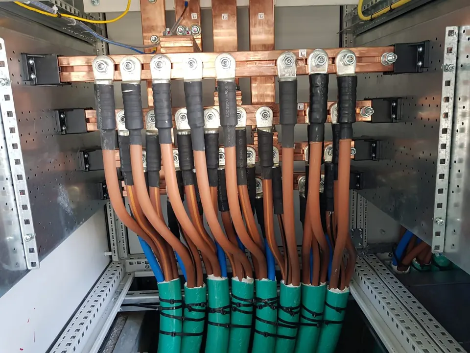
L1–L3 and N busbars in a switchboard 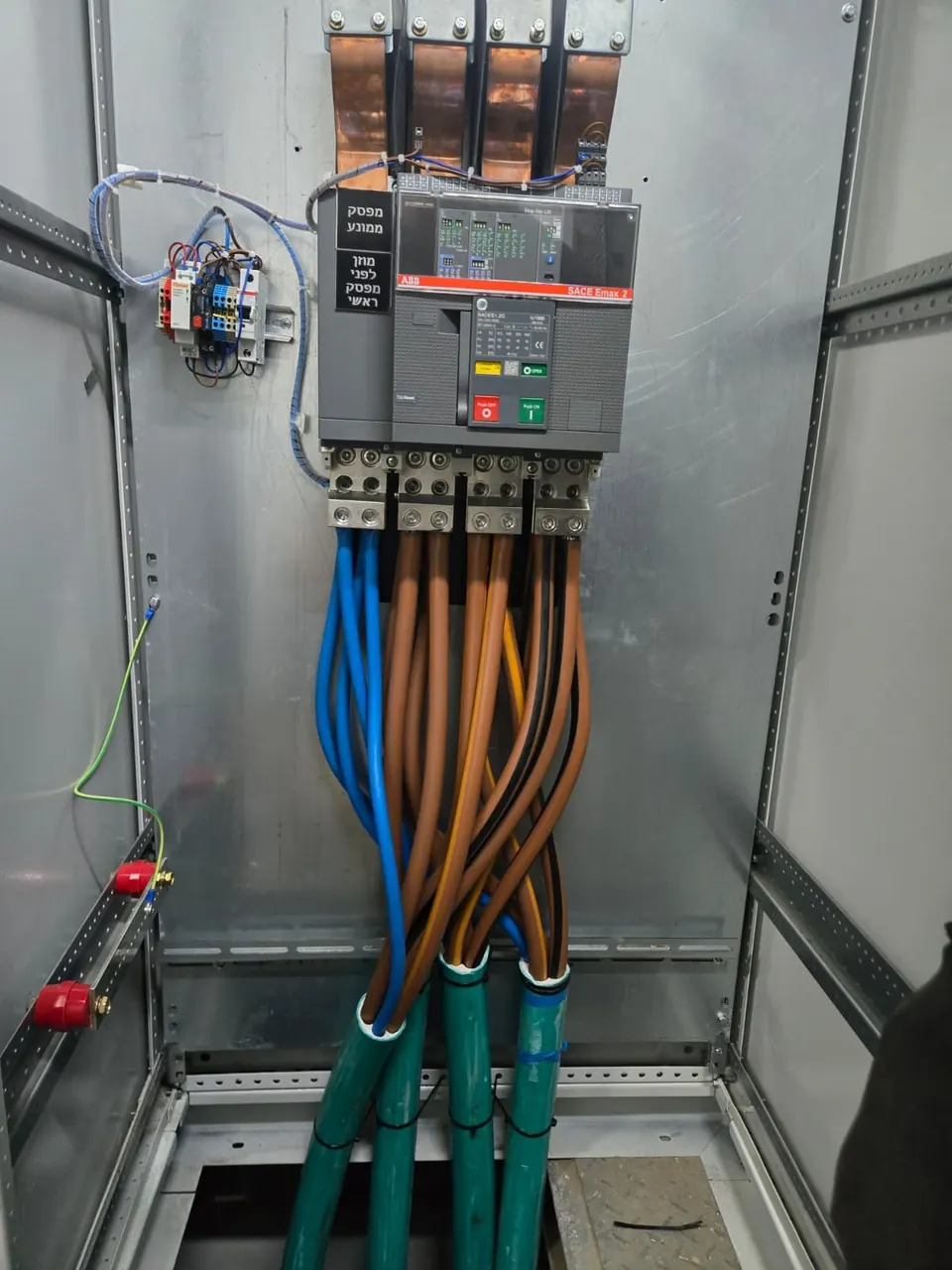
Motorised main breaker in a switchboard, labelled in Hebrew 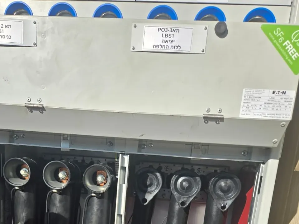
Medium-voltage cable terminations in switchgear cells Thermal image: a 96.8 °C hot spot at a cable connection against a 36.9 °C average 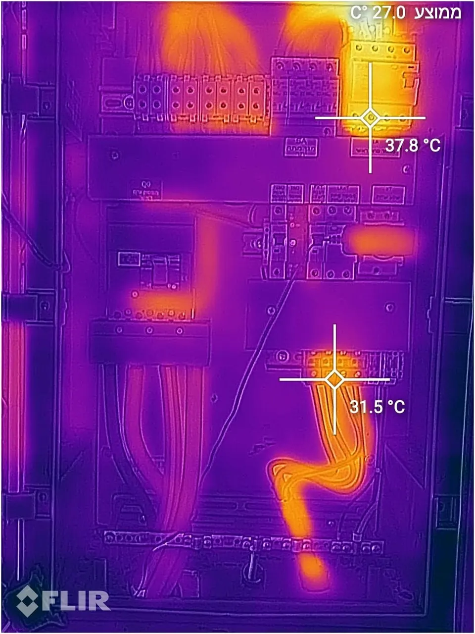
Thermal image of a healthy switchboard 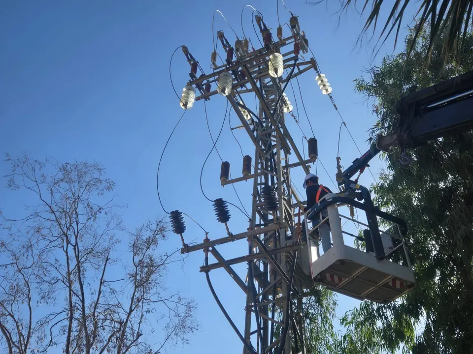
Work on a medium-voltage pole from a bucket lift 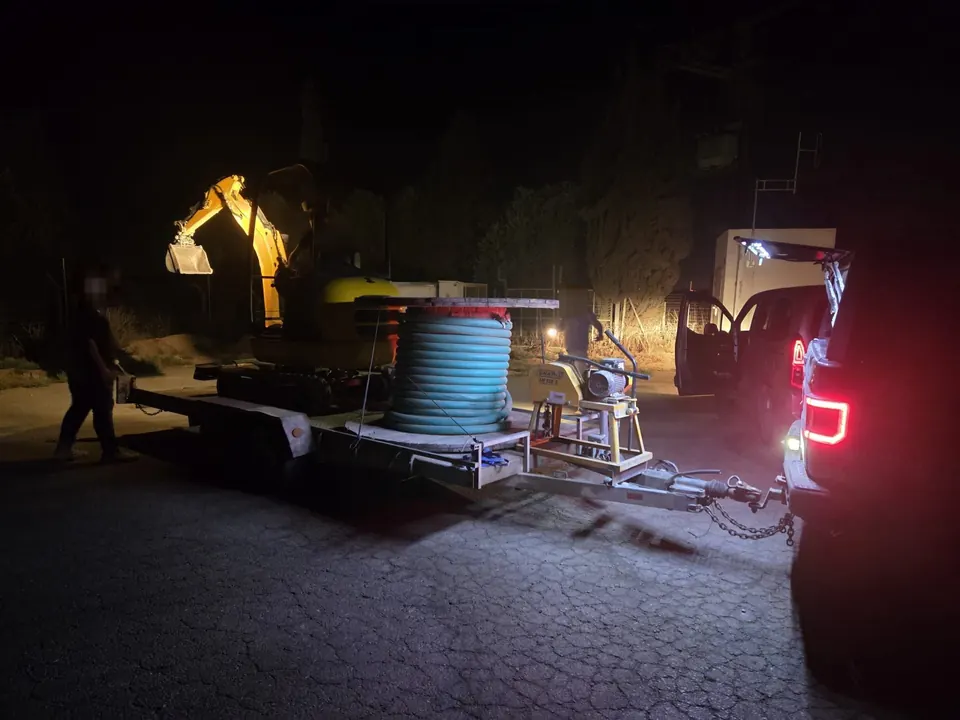
Cable work at night 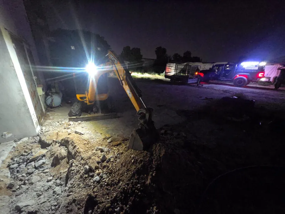
Trenching for a cable route at night
04 · FAQ
Frequently asked questions
How often should an installation be inspected?
The regulations set when an installation needs a periodic inspection, and how often, by the type of installation and its use, and the inspection itself is done by a licensed electrical inspector. For large switchboards we recommend adding periodic thermography, because it finds loose connections and overloaded components before they cause a fault. We can check what applies to your installation.
What is the difference between an RCD and a circuit breaker?
An RCD protects people: it detects leakage current, current escaping to earth, possibly through a person, and disconnects within a fraction of a second. A circuit breaker protects cables: it trips on overload and short circuit, so that the cable does not overheat and start a fire. The two complement each other, which is why an installation needs both.
Why does the RCD keep tripping?
An RCD trips when it detects leakage current. The cause can be a real leak, such as moisture, damaged insulation or a faulty appliance, or several small leaks from different appliances adding up. Either way, never bypass or disable it: it is the protection against electric shock. Call an electrician, who can find the source by measurement.
How do you know what utility connection size you need?
Start from the connected load of everything in the building, multiply by a diversity factor, since not everything runs at once, and allow for the power factor. The current per phase is I = P·1000·k ÷ (√3·400·PF), with P in kW, rounded up to a standard connection size. The simulator above lets you change the inputs and see the current and the recommended size. The final size is set with the utility, based on a detailed design.
CONTACT
Want to hear more?
Leave your details and we will come back with a proposal that fits your site.